|


| Bells and Birmans introduces you to Look here for Quality Custom Bell
Refurbishing
|
|


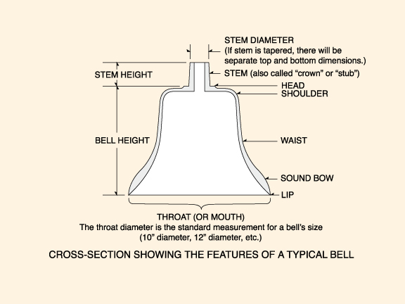
Cross section showing the features of a typical bell
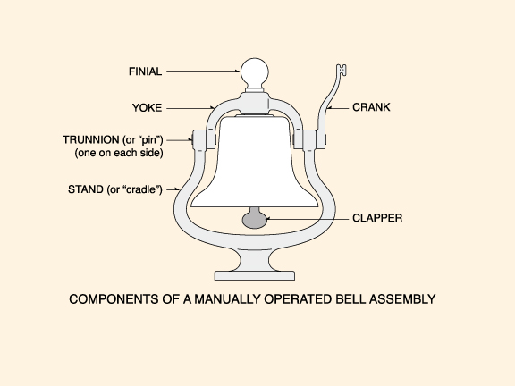
Components of a manually operated bell assembly
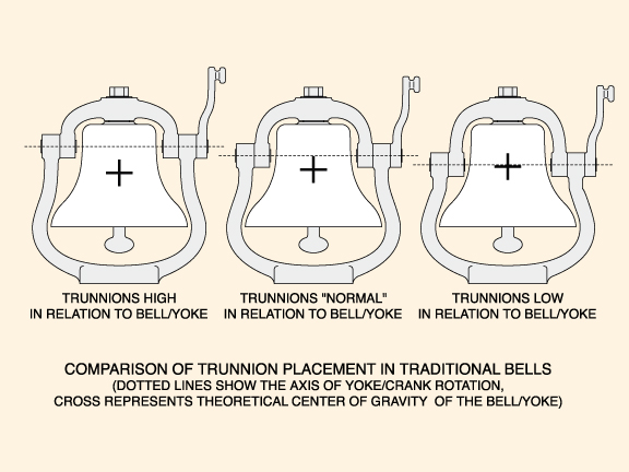
Trunnion Location
Generally speaking, the higher the trunnions are in relation to the center of gravity of the bell and yoke assembly, the more effort it will take to begin swinging the bell. Conversely, the lower the trunnions in relation to the bell/yoke CG, the less energy it will take to begin the swinging motion. Unfortunately, as the axis of the trunnions is further lowered towards the CG of the bell/yoke assembly, said assembly tends toward static balance; if this is actually achieved, the yoke/bell is then inherently unstable and is as likely to be upside down in the stand as it is to be right side up.
All bells of this type are set up with the trunnion axis high enough to keep the mouth of the bell pointing down when at rest, but some are much closer to instability than others. Certain U.S. railroads and/or manufacturers had bells which tended to "tilt" towards the front or rear when at rest, and these are generally found to have a relatively low trunnion axis which accentuated any weight imbalance in the bell casting itself.
The action of bell mounts with higher trunnions tend to be considered "ponderous," while lower trunnions might be considered "lively." The latter can become so extreme that it becomes difficult to achieve a pleasant cadence to the ringing. There is argument to this day as to where the perfect compromise is found (the disagreement has been going on for over 150 years).
If the turnnions are too high for a particular bell, sometimes improvement can be had by making a heavier finial to go on top of the nut, thus raising the CG of the bell/yoke. Sometimes reindexing the bell crank on its trunnion can make a difference, as can adding a crank to the other side of the bell (usually requiring a new, longer trunnion). After all this is digested, there remains the question fo where the clapper is pivoted in relation to the turnnion axis, and that complicates matters further. In theory, the best result is when the clapper pivot is on or above the same axis as the trunnions.
The wonderful "clang... clang... clang..." cadence we love to hear is a combination of bell construction characteristics and operator skill. Even at their best, pneumatic ringers are to bells what solenoid valves are to horns/whistles.
Article by Griffin Hamilton, used by permission of author.
ELECTRO-MOTIVE
DIVISION LOCOMOTIVE BELL IDENTIFICATION
Most locomotive bells offered to collectors in North America are from
diesel-electric locomotives produced by what until 2005 was known as the
Electro-Motive Division of General Motors Corporation, commonly referred to as "EMD."
General Motors Diesel, Ltd. - "GMD" - was the Canadian counterpart, and for our
purposes will be included under the EMD umbrella. Many of these bells and their
associated fittings have been mistakenly or deliberately confused with steam-era
bells, and the bulk of the following information was originally assembled to
help discourage erroneous identification.
I am not suggesting that 12" diameter steam locomotive bells do not exist,
because they do; they were, however, relatively uncommon except on narrow-gauge
or small industrial locomotives, and were considered somewhat undersized in
contemporary practice. Armed with the following information, the new collector
is much less likely to end up paying for a steam era bell while getting
something that came from a diesel-electric engine.
For new collectors interested in EMD bells from the get-go, I hope this helps to
identify components and provide a basis for understanding these bells a little
better. Be advised that EMD components are not readily available to people who
do not own locomotives; they do not sell parts to the general public, and their
jobbers may also have policies that preclude the average Joe from buying. Since
many parts described here were considered obsolete many years ago, the only
source for these will be on the secondhand or collector market.
(Please note that all part numbers are EMD numbers unless otherwise noted; in
situations where a vendor number is also given, the EMD number will be clearly
indicated to avoid confusion.)
BRONZE EMD
BELLS
Often called a "bell brass" or "AAR bell brass", all nonferrous 12" diameter
Electro-Motive bells were cast of a bronze alloy, and regardless of variation
they all carry the same EMD part number, which is #8004156 (the parts list
description being "BELL .. Locomotive - 12 inch", later adding the word "Bronze"
to differentiate them from the then-new cast steel bells). EMD bells with a 12
inch diameter mouth have an overall height of approximately 11 inches, the
latter measurement including a tapered stem having a 7/8" hole drilled through
its axis. Shapewise, this stem is a frustum that is approximately 2 inches in
height, the width being roughly 1.85" diameter at the bottom narrowing to 1.64"
at the top. Variations in manufacturing make these figures "more or less"
measurements, but they are close enough for a quick identification. On the
inside, EMD bells will have the area surrounding the 7/8" hole "spot faced" to a
diameter of roughly 2.500", creating a flat bearing surface to accommodate an
air ringer or an internal mounting. These stem and spot-face areas are the only
two locations on an EMD bell casting that actually undergo precise machining
operations.
The oldest EMD bells are generally unmarked and found with smooth (or "ground")
finishes. Although they may appear to be polished, closer examination of these
bells will exhibit indications of fine grinding. If a bell actually does have a
very high or mirror polish, be advised that it has probably been polished by a
motivated individual after removal from service, not by EMD or a common carrier.
The smooth EMD bells all have an appealing, traditional shape to them, and they
will also have a relatively sharp shoulder. This produces what is often called
the "flat top" profile, although the top is usually not actually flat, but runs
very slightly "downhill"Ö the shoulder may vary a bit in radius, but the basic
proportions are held across production.
Although they may look as if they have been profiled by a cutting tool in a
lathe, smooth EMD bells relied on a grinding process to achieve final form
(except for those machined stem and spot-faced areas already mentioned), so the
body of the bell is almost never truly concentric. Wall thickness can become
extremely thin at random locations if an EMD bell is chucked in a lathe and
actually cut with a tool, which is why it is not a recommended practice. More
than one EMD bell has had a hole cut or torn in the side while "taking a bit off
the outside." Has it been done successfully? Yes... but a successful job depends
on an optimal bell casting, the correct machining setup and a skilled person
doing the work.
By the late 1950ís, the finish of a locomotiveís bell had become unimportant to
Electro-Motive and most American railroads, thus the rough cast bronze bell
replaced the smooth bronze bell, making the latter obsolete. As their
description indicates, rough cast bells exhibit the texture of a typical sand
casting. Though interchangeable and dimensionally equivalent with smooth bells
where it counted, rough cast EMD bells have a somewhat less classic shape to
them, with subtle changes in profile; the most noticeable change is a much
larger radius at the shoulder. Because of this difference alone, a rough cast
bell can never be simply smoothed down and made into a "flat top" variant (one
would still need to add a lot of metal where none exists). EMD rough cast bells
almost invariably feature the initials "EMD" and the part number "8004156" cast
raised (or "intaglio," if you prefer) on their top surface. Both use
approximately 5/16" characters on earlier castings, the part number increasing
to 7/16" later on (leaving the initials still in the smaller size). Evidence
indicates that no factory-original EMD bell ever had a smooth finish in
conjunction with a cast raised part number, so any encountered should be
considered field modified.
The physical quality of any of the above types of bells varies a lot-- some are
quite good throughout, while others have a great number of casting flaws.
Whether smooth or rough, some bells were ground a bit more than usual in spots
to remove inclusions or some other problem with the casting, and the more
unfortunate ones may appear a tad "wavy" as a result... the smoother the
surface, the more noticeable this usually is. Relatively few castings will be
completely free of large voids, small pits, or areas ground away to remove some
type of flaw. The stem area in particular may often have noticeable casting
voids, yet such bells still generally hold up well in service.
Variations in castings play a large part in the tone of EMD bells, and there is
a considerable variation in sound between bells that appear identical. Two
random bells, cleaned and placed in identical mounts - and equipped with
identical ringers - are unlikely to be identical in. Get enough of them in one
place, and you will find close matches, but one point will stand: they are very
individualistic. It is an occasional frustration to have either a bell that
looks beautiful but sounds underwhelming, or a beat-up bell that rings
wonderfully. I own an older flat top bell that was treated very badly over the
years, but which has a marvelous amount of "sustain" to its ringing.
Keep in mind that 12" bells donít have the size (which generally equals power)
to rival their larger steam engine cousins. There will be no mistaking the
carrying power of an EMD bell for a 16" or larger locomotive bell, so keep
expectations realistic with regard to how "impressive" a 12" diesel bell is
actually going to sound when it is "all fixed up."
STEEL EMD BELLS
Available concurrently for a time (late 1970ís to early 1980ís), EMDís cast
steel bells (#8475495 "BELL .. Locomotive - 12 inch - Steel") replaced bronze
bells by the mid ë80ís, and are now the only option for new EMD locomotives
using air-operated bells. These bells are all rough cast finish, with the part
number cast raised on the top surface along with miscellaneous foundry marks.
Fully interchangeable, the dimensions and overall shape of these steel bells are
virtually identical to their rough cast bronze counterparts. They have a
naturally different tone than bronze bells, but are more than adequate for the
task they perform. Many new locomotives are coming from EMD with synthesized
(electronic) "bells," so the steel bell of traditional form should not be taken
for granted.
EMD locomotives can be found with replacement rough cast steel bells sold by
United Knitting Machines (UKM part #276-03845), and these will have "UKM" (along
with other markings) cast into the top surface; UKM bells are well made, very
serviceable and are good alternatives for anyone needing a "working" bell.
Most sellers are understandably reluctant to let a buyer scratch a bell just to
see what it is made of, so when in doubt, a simple magnet will let you know when
a ferrous casting is being contemplated.
OTHER BELLS ON
EMD LOCOMOTIVES
While it is not a common occurrence, EMD locomotives sometimes end up with non-EMD
bells. Apart from UKM replacement bells, Iíve seen very few "minority maker"
(which for many years meant anyone other than EMD) or "third party" bells on EMD
power in over twenty years of looking. Still, it does happen. I have seen a
cut-down and otherwise modified steam locomotive bell adapted to a working ICG "Paducah rebuild," which is proof that about anything is possible.
The early minority maker diesel bells were usually quite distinct from one
another, and are still fairly easy to spot as being non-EMD, even if you might
not know exactly who produced it. General Electric used some bells over the
years that were first cousins to EMD bells, but the most commonly encountered GE
bell today is a rough cast 12" steel bell. This bell has no stem, but rather a
"flat" surface on the top that allows it to be mounted under any convenient,
flat-bottomed projection. Various raised markings will be found cast in these
bells, sometimes on the inside. Recent practice on GE units is to weld this bell
to whatever it hangs from, but earlier ones were secured only via the nut
threaded onto the ringer stud.
Occasionally, one will run across a cast steel bell that has been ground to a
profile resembling a smooth EMD bell, but they are rare. All that I have seen
were unmarked and adapted to EMD mounts by a tapered bushing that the bell
snugged up against when the ringer nut was tightened. Just who made these bells,
or why, is not known to me at present. In any event, they do look fairly nice
when cleaned and painted. They are yet another good reason to have a magnet
handy.
Some smooth bronze bells that fit EMD mountings have been produced by other
parties, and the older examples are generally treated and valued much the same
as if they were original EMD bells. New bells closely following the EMD "flat
top" design are still available from a few sources (though not from EMD or those
handling new EMD parts), and are often the best bet for display purposes,
especially if a high polish is desired.
|
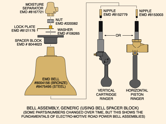
EMD BELL SPACER BLOCKS
For many years,
the standard bell mounting method on both passenger and freight EMD
applications was the cast iron "spacer block" (#8044623 "BLOCK .. Bell
spacer"). Though basically interchangeable and all marked "8044623" in
cast raised numbers, there have been at least two minor revisions to
this part; these subsequent variations may have an "A" added onto the
number, or they may have "REV A" or "REV B" cast into them on another
line. Various small foundry markings can also be found on many
specimens. Replacement spacer blocks were formerly available from Power
Parts Co., and they differed from EMD blocks in minor details such as a
part number using slightly different size/style of numerals. |
|
Brackets Using Spacer Blocks
On a locomotive, the spacer block alone does not constitute a complete mounting; the spacer block attaches to a bracket of some type (which in turn is generally welded to the locomotive, though occasionally bolted on). As a rule of thumb, EMD used 3/8" thick steel plate when fabricating brackets that utilize the bell spacer block, and these were often formed by bending and welding rather than welding alone, which makes duplication a heavy-duty chore. The more common ones are as follows:
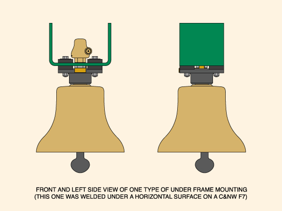 |
1. UNDERFRAME BRACKETS "Covered wagons" generally used a spacer block suspended from a piece of steel welded to the locomotive structure somewhere behind the pilot, and some road switchers also had their bells placed likewise. Some were welded to a vertical surface, and others under a horizontal surface, depending on the requirements of the locomotive. Bell placement seems to have been a contentious issue with some railroads, and older locomotives may have had the bell relocated one or more times in its life. Over time, the "generic" location for frame mounting became a location just inside of the frame sill forward of the fuel tank, although some units - like Southern Pacificís rebuilt SD "Cadillacs" - had the bracket centered on the rear face of the fuel tank.
|
|
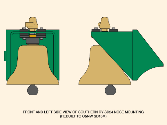
2. ROAD SWITCHER NOSE BRACKETS
First-generation
road switchers often had nose-mounted bells perched high up on the end
of either the long or short hood, using brackets projecting out past the
sheet metal; a few U.S. roads (N&W, Southern) persisted in nose-mounted
bells long after the practice disappeared elsewhere. Examples can differ
markedly between roads and models, and even among similar units,
different details will often be observed (curved gussets vs. straight
gussets, etc.). |
 |
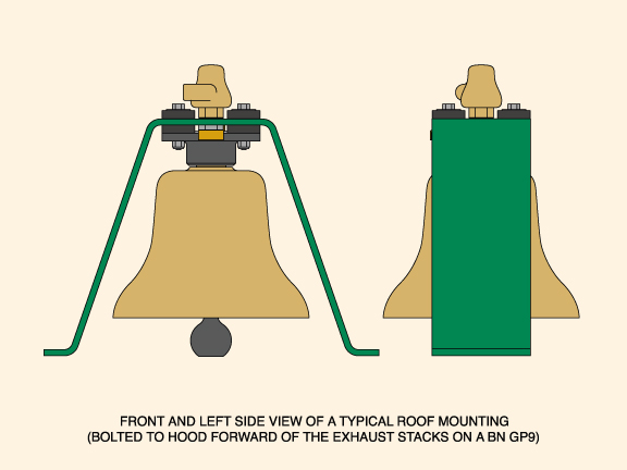 |
3. ROOF BRACKETS
Factory roof
brackets came in two basic styles: formed plate types often found on the
hood between exhausts, etc., and the pedestal (which will be discussed
separately). The formed plate types are of various dimensions, but are
generally of 6" wide x 3/8" thick steel plate bent to make a flat-topped
"A" with feet, the most consistent feature being the use of the bell
spacer block. There are numerous examples of railroad shops making their
own versions of these brackets, with some being better than others. Most
home-brewed imitations used thinner steel, with workmanship being
relatively crude in many instances. |
|
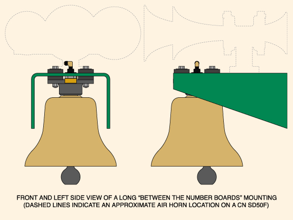
4. HOOD SIDE BRACKETS/BETWEEN THE NUMBER BOARDS BRACKETS There are
road switcher hood side brackets that use spacer blocks, and many times
they look like an underframe mounting that has simply been turned
upside-down. These were very common on IC/ICG and MoPac power; although
they vary in detail, they are much alike across the years, basically
nothing more than a gusseted plate projecting out from the side of the
hood. |
 |
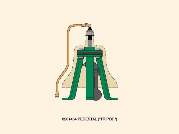 |
THE ROOF/HOOD PEDESTAL ("TRIPOD")
Here is where we
depart from mountings that use the spacer block. The pedestals (#8281454
"PEDESTAL .. Bell"), commonly called "tripods," are the "spacer
block-less" basic roof mount, and are basically little more than a ring
of steel with three 1.5" wide legs of 3/8" thick steel welded to it.
The pedestal alone is not enough to mount the bell: part #8281450
"ADAPTER .. Bell" and #8281451 "INSULATOR .. Bell" are required to make
a complete tripod. When assembled with certain ringers, the bottom of
the clapper will be below the plane of the pedestalís feet; clearance
for the clapperís swing depends on the tripod being bolted onto three
threaded "tapping pads" which are welded to the locomotive. Be aware
that ringers with a bevel on the outside of the clevis (such as the
Prime "106" single-action ringers) are more easily installed and removed
from tripod mounts than those without, because they can be rotated
without hitting the tripodís legs. |
END-CAB SWITCHER
MOUNTINGS:
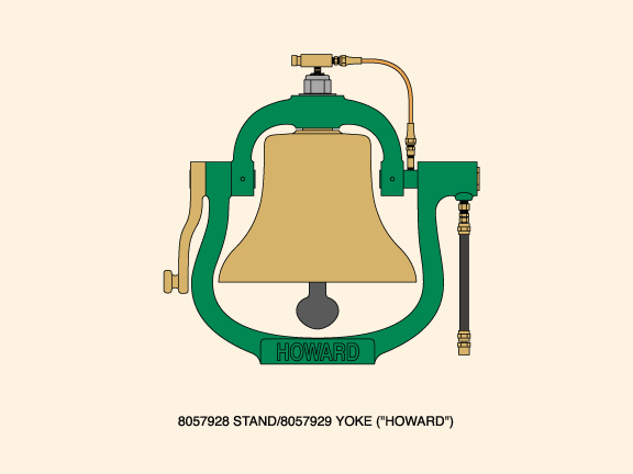
1. THE EARLY
SWITCHER STAND/YOKE ("HOWARD")
One of the earliest EMD bell mountings, though generally confined to end-cab
switchers from the 1930ís to the early 1950ís, was the "Howard" stand and yoke
(consisting of #8057928 "STAND .. Bell" and #8057929 "YOKE .. Bell"). This cast
iron assembly - also called a "harp" mount by some railroaders - looks and
swings like a steam-era counterpart, but is configured for pneumatic ringer
operation. The asymmetrical appearance of the stand results from being designed
to accommodate an air line emerging from the left trunnion. Howards come in a
few sub-variants, early ones with a lock plate riveted to the yoke, some with
patent information cast into the stand near the air inlet, etc. Generally
speaking, they will all say "HOWARD" on the mounting base. I have run across one
virtually unused stand/yoke that was lacking any markings other than the pattern
number on the yoke, and the stand had an angular projection added to the base
flange; this is the only radically different variant I have encountered, and I
was unfortunately not able to trace its history.
Howards operate correctly only when equipped with horizontal piston pneumatic
ringers that allow the clapper to swing fully in both directions. Photographic
evidence shows that many Howards ended up immobilized during their careers, with
the air line plumbed directly into the ringer instead of through the stand. If
nothing else, this allowed use of more common vertical cartridge ringers. So
regardless of ringer type, Howards can hold a bell in place even when frozen by
rust or made loose from wear. And wear is one of the Howardís common problems...
Howards that have seen long use frequently suffer from worn trunnions/holes,
resulting in a great deal of up-and-down "slop." Whether the bores in the stand
are worn larger or the trunnions are worn smaller - or both - they do tend to
open up with use. Excessive movement of this type may actually require line
boring and bushing to repair, so approach a badly worn Howard assembly
forewarned of a potential escalation of rebuilding cost/effort.
There is wide variety in the surface texture of Howard castings, some being
remarkably smooth while others are fairly rough (even for a sand casting).
Although Howard assemblies can be the crankiest of all EMD mountings and were
considered obsolete many decades ago, a few survive in service to this day.
Because they look like a steam-era bell mounting, Howards are very popular with
collectors, if not always with operators.
The Howard was no longer original equipment on switchers by the time rough cast
bells replaced smooth bells; should a Howard be found holding a rough cast bell,
one or the other is certain to be a replacement part.
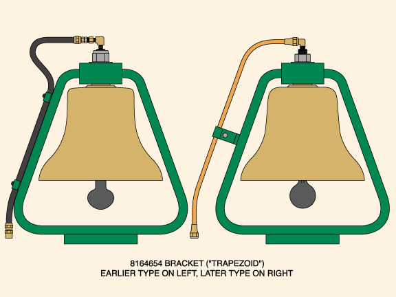
2. THE
FABRICATED SWITCHER BRACKET ("TRAPEZOID")
The "Howard" was replaced on EMD switchers in the early 1950ís by the fabricated
EMD "trapezoid" bracket (# 8164654 "BRACKET ASSEMBLY .. Bell"), which was the
standard end-cab switcher mounting until the end of 567-engined locomotive
production in the mid-1960ís. The earliest trapezoids featured two clamps
(bolted onto 1" x 1/4" x 20 tpi studs applied to the bracket with an
arc-stud-welding gun) for securing a flexible hose air line. The later type had
a single "clamp assembly" welded in place to secure a 3/8" copper tube air line.
Apparently EMD was not overly concerned with getting this clamp centered on the
bracket; while many are fairly well centered fore-and-aft, others are definitely
not. A general change between the two basic variants occurred somewhere in the
mid-1950ís, but overlapping occurred, with a few later operators specifying the
earlier type, particularly when a moisture separator was required (generally on
Canadian specification locomotives).
Over time, many of these studs or clamps become damaged to the point where they
are virtually gone or no longer serving any useful function. Methods of repair
vary enormously, running the gamut from correct replacement with factory parts
to field repairs using odd parts/placements... or complete removal. On rare
occasions, brackets with no indications of any original air line attachment
provisions are encountered, and these are likely to have been OEM replacements.
These brackets have a few idiosyncrasies of their own, one of which is a
"tilted" bell. Unless such a tilt is the obvious result of damage while in
service, the cause is often found to be the "block" portion - already bored to
take the bell stem - having been welded onto the "uprights" slightly out of
kilter. Occasionally, the bore itself was not perpendicular to the flats of the
block... if the two conditions were combined, things could get really out of
square! Most are not too bad, but some will jump right out at you... Iíve owned
both ends of the spectrum.
One minor but interesting observation is that rough cast bells often appear to
sit up higher in the trapezoid mounts than do smooth bells. This is generally an
illusion caused by the lack of a slope to the top of the rough cast bell. The
taper of the bellís stem and the matching bore in the trapezoid actually
determine how far the bell will draw up when tightened, but some rough cast
bells look alarmingly close when installed in these mounts.
The oval-plan base of these mountings is often found badly pitted on the bottom
surface because of moisture continually being trapped between the bracket and
the rubber vibration insulating pad (to be fair, Howards suffered the same
problem to some extent). Corrosion is also frequently found to be a problem in
the tapered hole for the bell stem. The base and uprights of this bracket are
fabricated of 3/4" thick steel; adding the 4" x 4" x 2" block at the top makes
this type of bracket fairly heavy, so by all means make sure whatever they rest
on can take the load.
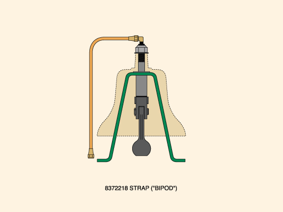
3. THE
645-ENGINE SWITCHER STRAP ("BIPOD")
The "trapezoid" was displaced by the two-legged strap "bipod" (#8372218 "STRAP
.. Bell mounting") in the mid-1960ís, and this is simply a piece of 2-1/2" x
3/8" strap steel bent into a flat-topped "A" shape with feet, the bell merely
sitting on top of it, rather than being suspended from it. The 7/8" hole drilled
in the top for a ringer stud is counter bored on the underside to reduce the
thickness of the strap in that area, otherwise the only machining is the
drilling of a few holes. This mounting uses one or more 15/16" I.D. x 2-1/4" O.D.
steel washers sandwiched between the bracket and the bell. Why "one or more?"
The edges of the "bipod" legs are a close fit up inside that bell, and if they
touch, the bell is no longer free to vibrate, thus its ability to ring is lost.
This is not an uncommon condition given the irregularity of bell castings.
Because of that close fit, a "bipod" is sometimes found with a bend or kink in
one or both legs, this having been done to keep the leg(s) from touching the
inside of the bell. Unfortunately, bending the legs can also lead to
difficulties in bolting the bipod to the corresponding mounting holes of the
locomotive, so it is not necessarily the optimal solution. Most bells can be
rotated on the mount until a position is found that will give sufficient
clearance between the inside of the bell and the edges of the bipodís legsÖ but
in some cases another washer (or two) may need to be added between the bipod and
the bell to raise the latter and gain the necessary clearance.
The bipod itself is fastened onto locomotives by 3/8 "-16 x 3/4" bolts threaded
into four steel tapping pads welded to the top of the engineís hood; this
mounting is typically found on SW1000/1001/1500 and MP15 locomotives, and not
much else.
VIBRATION
INSULATORS USED IN VARIOUS MOUNTINGS
Most EMD bell assemblies had some form of vibration control. All mountings
featuring bell spacer blocks utilized four rubber "insulators" (# 8024009
"INSULATOR .. Vibration") between the spacer block and the bracket, with four
more between the bracket and the washers for the mounting bolts. These eight
little "donuts" gave the bell assembly good vibration dampening and a degree of
flexibility that helped prevent problems that can plague bells in excessively
rigid mountings.
For many of us, it is hard to get the rubber vibration insulators used with
spacer blocks. The good news is that we can make them out of 1/2" thick neoprene
stock: they are 2" in diameter, with a 9/16" hole through the center. Youíll
need eight of them altogether.
The "tripod" pedestals use a large, steel-encircled round neoprene insulator
between the pedestal and the adaptor, much like an oversized EMD air horn
vibration insulator/mounting pad. Being somewhat protected from the elements by
their location up inside the bell; these remain fairly resilient over long
periods of time, although the outside steel ring is often a bit rusted.
Both "Howards" and "trapezoids" sat on a 1" thick neoprene pad, oval in shape to
match the footprint of the bases. Most of these applications also had a
marine-grade plywood filler piece below this pad, the plywood being slightly "V"
beveled on the underside to fit the shallow "peak" in the top of the switcherís
hood. After decades of use, these particular insulators will generally harden,
shrink or rot to the point where the bell assemblies will loosen and "rock"
while the locomotive is moving, even after retightening.
Until recently, the "bipod" strap mounting was unique in the EMD line insofar as
it had no vibration insulators at all, the vibration supposedly being controlled
by the less rigid strap itself, in conjunction with the minimal four-point
attachment to a relatively flexible sheet metal hood. Some of the newer EMD road
switchers have their steel bells welded right to the locomotive... so much for
vibration control!
MOISTURE
SEPARATORS FOR EMD BELL ASSEMBLIES
Many EMD bell assemblies feature a moisture separator that looks a bit like a
miniature bell applied to the end of the bell ringer stud. Often mistakenly
dismissed as just an "air fitting," it is really a cleverly designed casting
that does more than just connect the air line with the ringer. The separator (EMD
# 8167721 "SEPARATOR.. Moisture"; Vapor part #16720048; Viloco part #BR-113)
will be marked "VILOCO BR 113" and have the word "INLET" near the 1/4" NPT port.
Air enters the port from the supply line and swirls around the inside of the
lower chamber of the separator where centrifugal force causes moisture in the
incoming air to coalesce and spit out of a .052" dia. bleed port. The air then
flows to the upper chamber, the apex of which just clears a pipe nipple or pipe
assembly screwed into the end of the tapped air passage in the ringer stud. The
- somewhat drier - air flows over the top edge of this pipe nipple and down into
the ringer itself.
These moisture separators changed from cast bronze to cast aluminum over the
years, even though they kept the same part number. Whether made of aluminum or
bronze, these were not polished as originally installed. Many locomotives lost
these separators after the passage of time, as they werenít absolutely necessary
for the bell to operate. Bells on old units often ended up with common brass or
steel air fittings threaded into the top of the ringer stud.
Moisture separators were less common in second-generation and later hood and
roof mountings, particularly with bells using "trapezoid," "tripod" and "bipod"
brackets. Broadly speaking, only
Canadian-influenced railroads seem to have favored separators on these
applications. Bell assemblies using "Howard" mountings nearly always had needle
valves installed at the top of their ringer studs, so they were hardly ever
found with separators.
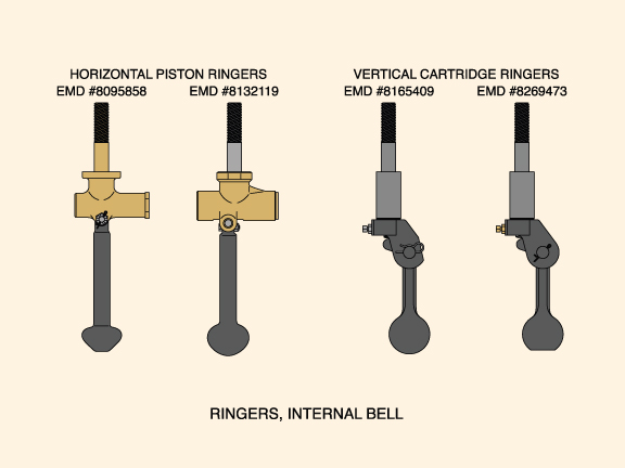
INTERNAL BELL
RINGERS
EMD has always used ringers designed specifically for use with compressed air,
not steam. There have been two basic configurations used, which we will call
horizontal piston ringers and vertical cartridge ringers; both are available in
single-action or double-action variants. Single-action ringers depend on the air
being utilized only on the power stroke, relying on the momentum of the
returning clapper for the return to battery; double-action ringers use the air
to actually assist the return part of the operation.
Do not take seriously anyoneís description of a locomotive bell being a
"Graham-White," "Prime-Milw," "Salem 506" or "Viloco Chicago" bell, because
those cast-in markings only identify the ringer. And with that, letís identify
some ringers.
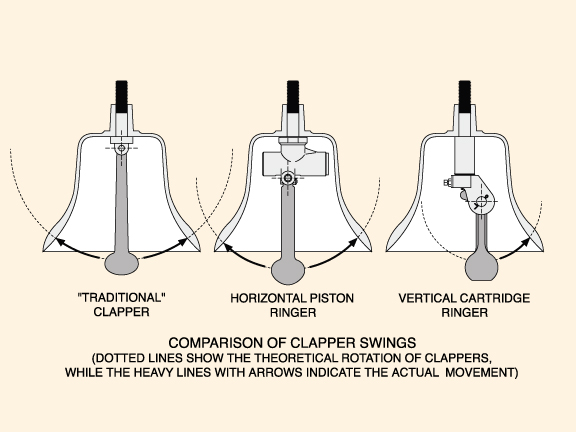
1. HORIZONTAL
PISTON RINGERS
In a horizontal piston ringer, the operating piston moves in the horizontal
plane, and the clapper is centrally pivoted, allowing the clapper to swing fully
in both directions of travel. This full bi-directional travel was a critical
consideration in "Howard" mountings, but is mostly unnecessary in other EMD bell
assemblies.
The common early horizontal piston ringers used by EMD were single action
ringers having a one-piece bronze ringer stud and body casting (#8095868 "RINGER
.. Internal bell") featuring a vertical groove - for a small toothed lock plate
- running the length of the studís threads. The end cap retaining the piston is
octagonal on these very early models, which helps to identify them.
This ringer was superseded in the early 1950ís by an improved model from Viloco
(EMD #8132119 "RINGER .. Internal bell"; Viloco part #30312; Vapor part
#16730160-01) which featured a separable stud and body, and which used a round
end cap having two holes for a spanner wrench. These Viloco single-action
ringers were the most popular horizontal-piston ringers, and are common enough
even into the 21st century; they may or may not have a needle valve fitted to
the air inlet at the top, those used in Howard mountings being more likely to
have one of the three different needle valves EMD listed over the years.
Viloco eventually developed a double-action version of their ringer, which had
limited application in later Electro-Motive power (EMD part #8205243 "RINGER ..
Internal bell - Double action"; Viloco part #30472; Vapor part #16730161-01).
These can be quickly identified by the words
"DOUBLE ACTION" cast in the ringer body. The stud and the clapper are
interchangeable between this ringer and the earlier single-action version.
2. VERTICAL
CARTRIDGE RINGERS
Vertical cartridge type ringers were applied to EMD engines as far back as the
early 1950ís, beginning with the single action "BR-106" (#8165409 "RINGER ..
Internal bell"). Later on, this part had the addition of "Single-action" added
to the description to differentiate it from the "BR-106P" (#8254433 "RINGER ..
Internal bell - Double action") ringer. The difference was in the cartridge, all
other components being the same. Ringers of the "106" type have been made by
Prime (now part of the Dayton-Phoenix Group) and by Graham-White (also known as
Salem, since Graham-White refers to its products as "The Salem Line").
There are a great number of visually similar ringers as made by Prime and
Graham-White, differing mainly in the cartridge type (whether single-action or
double-action). While interchangeable across most applications, these ringers do
have a few interesting differences that may make a difference-- for example, the
Prime "106" has an additional bevel on the clevis which makes installation and
removal from "tripodí and "bipod" brackets easier. Even within some given
models, there have been variations such as decreasing the overall length of the
clapper on the "506" by removing a portion from the bottom, leaving a "flat"
there.
A lot of older units that were retired in the 1980ís and 1990ís still used the
"106" ringer, and it is appropriate for most pre-1972 locomotives. The "506"
ringer is usually found in more recent EMD applications, and this is a
double-action ringer (#8269473) which has supplemented or superseded most of the
others. Though they may or may not be the original equipment for any given
example, all of the ringers just discussed can be found inside an EMD 12" bell.
They will all fit, they will all make their clapper strike the bell properly,
and most railroads had more than one type on hand over the years.
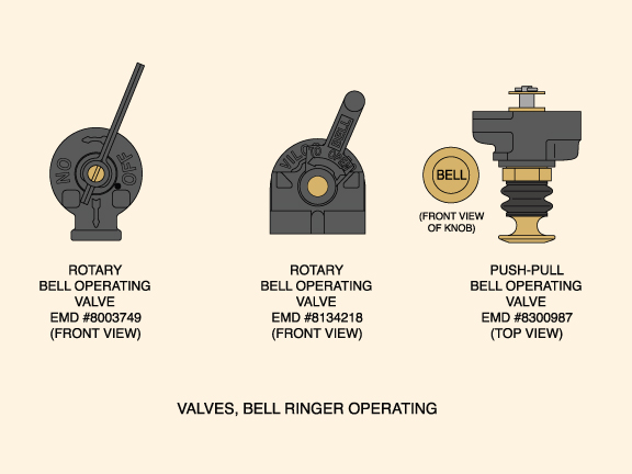
BELL
OPERATING VALVES
Some older air brake schedules (such as 6BL) will have the bell operating valve
(at one time called the "bell ringer throttle valve") as a component of the
brake pedestal; later EMD power may have solenoid-operated valves, but both of
these are beyond the scope of this guide. Like the ringers, bell operating
valves are designed for air only. EMD has used a number of "stand alone" valves,
and the following will be the most often encountered:
1. ROTARY
VALVES
The older of the two commonly found rotary valves (#8003749 "VALVE .. Bell
ringer throttle") was a small cast iron unit having a short handle with the word
"BELL" cast in or stamped on it, depending on the handle variant (I have
generally run across the pressed steel handles with the word stamped on both
sides). Most specimens of this valve will have the makerís name or initials cast
raised on the rear of the unit, such as "THE U.S. METALLIC PACKING CO." This
valve is easily identified as it has only one air port on the bottom and one
port at the rear.
The later rotary valve (#8134218 "VALVE .. Bell ringer throttle") was similar in
nature to the above, but was a bit larger, with a cast short handle (in either
bronze or iron) having "BELL" in raised letters inside a recessed area. This
valve is quickly differentiated from the earlier type by its having two air
ports on the bottom and one at the rear. This valve was made by Viloco (Viloco
part #100, Vapor part #16720039), and is usually found with "VILOCO 350" cast
raised on the front of the unit, although on some production the "350" pattern
number may be milled away and the "100" part number stamped in its place.
Both of these valves depend on a spring to press a bronze disc against a cast
iron valve body cap in order to seal properly; no o-rings are used.
2. PUSH-PULL
VALVES
The "push-pull" type of bell operating valve comes in many varieties, but they
all consist of a knob/cartridge assembly screwed into a cast iron body of some
sort (usually a single cartridge body, but occasionally they are found in bodies
accepting up to four different valve cartridges for controlling different
items). The inlet and outlet on the body may be oriented top and bottom, or both
to the rear... and the cartridges may be manual, 3-way (both manual and
automatic), and so on.
One of the most common types is the simple manual operating valve (#8300987
"VALVE .. Bell operating - Push pull type - GWS-616-1A-BH") having a brass knob
stamped "BELL" on its face. The knob pulls out to activate the bell, and pushes
in to stop. A rubber dust boot extends between the front of the cartridge and
the knob, and is often found damaged or missing after extended use.
These valves use o-rings which can be renewed to restore function; rarely will
one become so worn that it canít be made to work by simply cleaning and
replacing any worn or brittle rubber components.
BELL
RINGER OPERATION AND PECULIARITIES
All of the ringers in EMD bells depended on compressed air from the engine's
main reservoir (at 133 psi, more or less) to actuate a piston of some sort (a
stand-alone piston in the horizontal piston ringers, or a piston within a
cartridge in the vertical cartridge ringer). Reciprocation of the piston is
enabled by some portion of that air being exhausted out a hole or port, after
which the process begins all over again.
Basically, the operator opens the bell operating valve (or "throttle") in the
cab, air pressure builds in the ringer, the piston moves due to that pressure,
and it in turn moves the clapper until the bell is struck. At some point during
all this movement, the piston has traveled to a position where its air exhaust
port can vent to the outside atmosphere; the pressure behind the piston then
drops, and the force of the rebounding clapper (and/or air acting on the piston
itself if it is a double-acting type) moves the piston back to its original
position. The pressure builds again, and the cycle continues until the operator
cuts the air off at the operating valve.
The ringing rhythm ("cadence") depends on a couple of factors, with different
ringers and installations giving different cadences. The size of the air ports
(intake and/or exhaust) makes a difference, as does the air pressure. There is a
balancing act between flow and pressure, with both ringer speed and power of
attack variable within a nominal range. Some applications in the past (almost
always using horizontal piston ringers) relied on a needle valve applied to the
ringer stem to adjust the cadence, but their use has mostly been abandoned.
Horizontal piston ringers exhaust the expended air out through the large
rectangular slot in the bottom of their ringer bodies, while the vertical
cartridge ringers more or less blow the exhaust out of tiny ports in the lower
part of the cartridgeís piston. The exhaust air will also blow out the correct
ringer lubricants over time, as well as whatever contaminants are circulating
through the locomotiveís air system. What contaminants, you may ask?
An engine that has oil leaking from the compressor will have some of that oil
show up in the ringer; an engine with excess moisture in the air supply will
contribute water to the ringer. The former seems to be more of a problem in
contributing to the build up of filth on the outside of the ringer and the
inside of the bell, while the latter will often freeze up a ringer in sub-zero
temperatures. Any oils that happen to leave the ringer and settle on the inside
of the bell will attract dust, soot, etc.; over time, this sludge can build to a
surprising thickness.
The rotary operating valves had oiling ports in them, and back in the days when
horizontal piston ringers and high nose mounts were state-of-the-art, some
locomotives also had an "oiler" in the air line near the operating valve. By
opening the tap, squirting some oil into the line and then closing the tap, oil
was introduced to the ringer from the comfort of the cab, and that oil
eventually blew its way to the ringer... more or less. The possibilities for
contamination were about what one might expect, and the practice lost favor with
the ascendance of the vertical cartridge ringer.
Solid contaminants are a nuisance in either type of ringer, but the vertical
cartridge ringers use far smaller orifice sizes to meter the air, so they
require some form of dealing with particulates. Some cartridges will use a
"self-cleaning" rod sliding through a close-fitting orifice, while the majority
have a small piece of metal screen on the underside of a metering orifice (which
looks like a hex plug with a really - REALLY - tiny hole through the center).
This screen may become clogged with debris, in which case it can be soaked in
solvent and then blown clean with compressed air. Generally speaking, a thorough
cleaning and/or o-ring replacement puts most ringers back in action, but an old
ringer may become worn to the point where it will simply no longer function
properly without parts replacement or more extensive work (building up with
weld, bushing, lining, etc.).
Air ringers in bells that have been removed from railroad service and stuck on
someoneís porch (or a pole out in the yard) sometimes exhibit a drilled hole,
eyebolt, or some type of stirrup that has been added to allow manual ringing by
a cord/rope. These are home-brew modifications, and I recommend undoing them if
the ringer is still salvageable. Exceptionally old or uncommon ringers (such as
the early horizontal piston varieties) can be worth having an expert repair them
- or at the least provide salvageable parts - so donít automatically toss them
in the garbage even if you intend to replace them with new ringers.
RINGER NUTS AND
WASHERS
The different ringers and mountings on EMD bells have always used some type of
7/8 x 9 ringer nut, ranging from heavy hex thick plain nuts, to Flexloc lock
nuts, and even nylon-insert stop nuts. All of these had differing overall
heights and widths, as do the two kinds of 7/8" washers found in EMD bell
assemblies. Also take into consideration the thickness of a lock plate if one
was used, add or subtract the variations in the overall length of the bell
brassí ringer bore, and it will become apparent that some combinations may leave
too few threads on the ringer stud for proper use of a moisture separator.
Now a word about lock washers... is/was there a split or toothed 7/8" I.D. lock
washer under the nut of your bell? If so, it shouldnít be there... someone added
that after the bell left La Grange. Donít pay it much attention, and when
everything is apart, toss it away. EMD bell ringers and 7/8" lock washers are
mutually exclusive; one handy rule of EMD bells is that the only washer you need
between the ringer nut and the bell will be either a plain one of 15/16" ID x
2-1/4" OD (on spacer block, Howard or trapezoid mountings), or a plain one of
15/16" ID x 1-3/4" OD (as used on tripod or bipod mountings).
(A further note of clarification: while EMD refers to such washers as 7/8" plain
washers, they have an actual ID of 15/16". Basically, we are discussing a "USS"
washer for most applications and the smaller "SAE" washer for use on top of the
bell stem when using tripod and bipod mounts.)
LOOSE, LEAKING OR
POORLY LINED-UP MOISTURE SEPARATORS
Moisture separators are not a real tight fit on most ringer studs, and trying to
get a seal by tightening them down against the ringer nut is bad form... besides
which they seem to almost never "line up" right with an existing air line.
Rather than risking stripped threads or otherwise messing them up, I have found
that simply placing an o-ring of 13/16" ID between the moisture separator and
the ringer nut can help cut down on both looseness and leakage with separators
when either is a problem. O-rings of different wall thickness should be tried
for any given bell; one of them generally allows the separator to be properly
indexed for any existing air line.
REMOVING EMD BELL BRASSES FROM MOUNTINGS
Oftentimes, the first question or problem people have is simply how to get the
bell assembly apart. If the assembly has been together for a long time, things
are usually going to be firmly in place and determined to remain that way. There
is no harm in soaking the whole thing in a penetrating oil for a couple of days,
and by that, I donít mean just a squirt here and there. Really wet it down and
let it sit, and renew the penetrant if it starts to dry off.
The first big step is to remove the nut that holds everything together, and that
is the large one that is threaded onto the top of the ringer stud. Right here
and now, make a note of what kind of nut is used, and measure both the overall
height and the width across the flats. Is it a heavy thick one compared to the
normal hardware store variety 7/8 x 9 nut? Is it a Flexloc or Stover lock nut?
Is it a nylon insert stop nut (they were often found with Viloco ringers)? Just
be aware that there are rights and wrongs in different applications, and the
right nut can be important to a correct rebuilding/restoration.
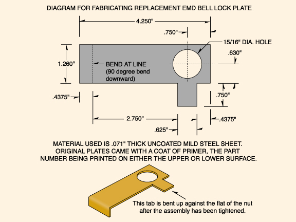
If there is a lock plate with the "tab" bent up against the nut, try carefully
bending the tab down far enough so the nut has just enough clearance to turn...
this way, the lock plate might still be salvaged for reuse. If the tab on the
lock plate has been bent more than once or twice, it is likely to fatigue crack
and thus be unusable, but the remains can still be valuable as a pattern for
making a duplicate.
Getting back to that big nut, I will say that a little heat on the nut can help
loosen things as long as the nut gets heated up fast enough that the stud
remains relatively cool. Just keep in mind that the bronze bell stem is probably
less than 1/4" away from the nut, and heat transfers through metal mighty fast.
One of the common problems encountered in removing the nut is that the ringer
stud (and/or ringer) may start to turn; unfortunately, there is no 100% perfect
way to ensure the ringer doesnít turn, and that includes grabbing the clapper
and keeping it in place with all the leverage you can. With the really old
horizontal piston ringers having one piece stud and body construction, it is
fairly simple to keep everything from turning, as you can pretty much grab the
ringer body and hold it without trouble. These ringers are now fairly rare and
replacement parts are virtually nonexistent, so it would still be wise to take
extra care with them when attempting disassembly. They use an odd little "lobed"
lock plate and rivet when used in a Howard application, and those items are to
be preserved whenever possible.
Viloco horizontal piston ringer bodies may simply start to unscrew from the
ringer stud, leaving the stud to be carefully driven up and out of the bell,
leaving the nut on the stud. That is not the worst scenario you can have, but
even so, it is likely that the nut will eventually have to be removed from the
stud. My advice in these cases is to do what it takes to save the stud, bearing
in mind that the nut is nothing special and can be replaced through a
well-stocked fastener company, while the Viloco stud is no longer available as a
factory replacement part.
Vertical cartridge ringers have a one-piece ringer stud/motor housing that holds
everything together, but the clevis for the clapper screws onto it. This can be
a problem because when trying to get the nut off, the clevis wants to unscrew,
and it seems to almost always loosen before the nut will. The 5/16" x 18 set
screw that indexes the clevis on the stud is not meant to take a horrendous
amount of sideways guff... such as strong-arming the ringer by the clapper. Use
a judicious amount of force, and keep in mind that if the set screw meets the
threaded lower part of the ringer stud/motor housing, threads may get all
boogered up.
One solution is removing the clevis and using an inside pipe wrench or expanding
mandrel, while others use a regular pipe wrench at an angle, neither of which
has worked particularly well for me (especially the latter). If the stud/motor
housing is in bad shape due to severe pitting or has been otherwise damaged
beyond salvaging, feel free to hold it securely with whatever works, because
they are still available as a spare part (and are included in a complete ringer
assembly if you need/decide to replace the ringer).
In my own experience, an old and rusted nut is often best removed by carefully
drilling through the nut from the top - taking care to miss the ringerís threads
by a hair, and stopping just before drilling into the lock plate or washer -
then spreading the nut with a chisel. Drill two holes down through the nut, 180
degrees apart, and then split the nut with the chisel down one or both sides as
needed. This is time-consuming and requires care, but it will get things apart
and still preserve the stud. If you can use a large, floor-model drill press or
a large milling machine to do this, you will be way ahead of the game. The
tapered tops of Flexloc or Stover locknuts make them difficult to drill, but
with care, they can still be removed in this manner.
Of course, if the ringer stud is already somehow damaged beyond repair, then one
could always cut the nut off and not worry about messing up the stud. A lot of
bells and mountings have been irreparably ruined by cutting torches though, so I
donít recommend their use... but if you are a true wizard in that game, you pays
your money and you takes your chances.
Once the nut has been removed (one way or another) and the ringer stud is out of
the bell, there remains little in the way of tough work, unless you have a bell
that is in certain mountings. The problem is, the majority of EMD bells were
originally in one of these "certain mountings": the spacer block, the trapezoid
or the Howard. The tapered stem of the bell fits inside a corresponding tapered
bore in these mountings, and the action of tightening the nut on the bell ringer
stud draws the bell tightly into contact with the walls of this bore. Some of
them will be in there - to put it mildly - pretty doggone tight. Even a brand
new bell assembly that has just been snugged up will often require a tap to
break loose, so you can anticipate some effort on the ones that have been in
place a long time.
Of the three "difficult" types just mentioned, the Howard mountings are often
the easiest to get the bell out of, because the tapered bore in the yoke casting
only contacts the bellís stem for a depth of about a half an inch at both the
top and the bottom-- that leaves less surface between them for "adhesion." The
other two types have full contact for nearly the entire length of the bore.
Something to remember with any of them is that you should not use a screwdriver,
chisel or other wedge to try and remove the bell. Lots of damage has been done
by sticking something in the narrow space between the bellís head and these
mountings, then attempting to "wedge" the two apart. At best, the bell will come
out but be noticeably marred; at worst, the bell will have a hairline fracture
or be slightly deformed.
A proper puller (such as used for removing pulleys, etc. from shafts) will work,
but sometimes requires a bit of cobbling to get situated for pulling without
doing damage. Cast iron spacer blocks need more support than just out at the
very edges, or they may crack. Whatever is come up with, do try to keep from
messing up the bell brass at the top of the stem.
One field expedient is solidly supporting the mounting in such a way that the
bell is free to hang and the lip is approximately 1/2" off a sturdy, padded
surface sufficient to safely catch a falling bell and keep it from damage. Some
people use sections of 2" x 4" lumber to rig things up, and I have done just
that myself. A short brass or aluminum rod, or good hardwood dowel approximately
1-1/2" in diameter can then be placed solidly against the top of the bell stem
(which will be within 3/16" or so of being flush with the top of the bore
through the mount) and struck smartly. Never hit the stem of the bell directly
with the hammer or any other steel tool! Take care to clean the top of the stem
before striking to prevent embedding dirt or scale in the bronze, and avoid
"battering" the metal. It may take a few blows to break things loose, and I have
found over the years that a larger hammer is better (up to a point).
Here is a good place to insert a safety warning: BE VERY CAREFUL to keep hands
and feet away from the lip of the bell when trying to remove it, because when
the bell finally breaks free, it will do so INSTANTLY, and the taper of the
parts insures that the bell will free fall... in other words, your reaction time
will not be sufficient to deal with 40-odd pounds of metal having a relatively
sharp lip on the bottom. Take it from me... they come off with a "pop" and hit
the ground RIGHT NOW. If you want to meet emergency room staff, having the lip
of an EMD bell drop on your foot is an excellent expedien
RANDOM THOUGHTS ON EMD BELLS
COMMON STRUCTURAL DAMAGE
Railroading has always been tough on equipment, and diesel-electric locomotive
bells are cut no slack in that regard. The fact that there are half-century-old
EMD bells in revenue service is a testimony to the overall design of these
bells, but as with all things, "stuff happens." When a bell is damaged in a
major incident and is either all torn up or no longer truly functional, it is
usually fit for nothing but the recycled metal pile. Railroads replaced bells
that were too shot to trust, and the average collector will do well to avoid
bells with obvious serious damage. Bells will get bent out of whack because of
collision, derailment, shop accident or ham-handed attempts at removal, yet they
can still perform as intended. Bells that are damaged but still functional
require assessment on a case by case basis.
The stem of the bell - perhaps more accurately, the junction of the stem and the
head area - is a location where damage is frequently noticed in an EMD bell. EMD
bells in Howards, trapezoids and all spacer block applications are held in the
mountings by the stem of the bell, and the head (the flat annular "step" of the
bell immediately below the stem) should not touch the mountings. The gap between
the head and the bottom of the spacer block - as well as the Howardís yoke or
the trapezoidís "block" section - will vary, but generally ranges from 1/16" to
3/16". This gap is deliberate, and is the consequence of the tapered fit of the
stem in its mount; EMD bells and mounts should never be modified to cause the
head of the bell to "bottom out" on the corresponding mount.
One of the consequences of said gap is that when the bell is struck by a very
strong sideways force (like a sideswipe, or perhaps even dropping a switcher
bell assembly from the locomotive to a hard surface), the bell has a tendency to
bend at the juncture of the stem and the head, as the aforementioned gap allows
bell to be displaced at a slight angle. In castings where the wall thickness is
thin at the top of the bell, the metal just outside of the head may deform
instead; bells that received a deeper spot-facing operation around the ringer
hole are also prone to bending in this area first. A powerful blow can actually
fracture or tear the metal on the side that took the hit.
In bells mounted to the locomotive frame via a spacer block, severe pressure
from above or below can fold the top of the bell up around the bottom of the
mounting, or break the bell completely through around the top (the stem and
spacer block acting as a giant stationary punch). Such damage is usually only
seen when a bell has gotten in the way during a derailment or shop accident, and
the lip of the bell has come down on some large object (such as the front truck,
allowing a great amount of the engineís weight to be transferred to the bell). I
have seen a C&NW (ex-Rock Island) GP7ís bell folded up so severely that the top
of the bell brass was almost one half inch higher than the bottom of the spacer
block. Amazingly, the bell did not appear to be fractured, and it still
functioned (after a fashion)... it looked pretty awful though! Most bells simply
would not survive such an ordeal.
Whatever the cause of damage, bending of the bell brass is very slight as a
general rule of thumb, but some victims of circumstance will be found badly out
of line... and some may have a fracture as well. My advice is to leave the
latter alone, as their value may not be much more than what the metal dealer
will give you for first-class copper-based alloys. If the bend is very slight,
then the bell is probably still serviceable... it just wonít take "best of
show." I have been told that some bells can be "straightened out," but I have
yet to see the job actually done successfully, and would not take on the task
myself.
Another stem-related issue is crevice corrosion at the juncture of the stem and
the head of the bell. If a debris/moisture "poultice" (It can be dirt, soot,
crankcase drippings and the proverbial kitchen sink combined with water) was
allowed to remain in that narrow gap between the head of the bell and the bottom
of the spacer block/trapezoid/Howard yoke, corrosion may have occurred in this
area. One should examine any instances carefully to make sure it is simple
galvanic corrosion and not a serious fissure due to fracturing or stress
corrosion. I will add here that the gap between a spacer block and a lock plate
is another area that lends itself to such "birdís nests" of corrosive crud, but
rarely will the pitting lead to structural problems with the spacer block; the
lock plate may, however, be eaten all the way through over time.
Some EMD bells that have been in active train service will be found extensively
marred by someone "hammering" on the outside of them. This damage is often
concentrated on one side, more-or-less at the point of easiest access. Such
damage was frequently made by trainmen hammering on the bell - often with an air
brake wrench - to try and free up a balking ringer or a bell full of ice/snow
(such "field repair" was also often applied to air horns). Only the buyer can
determine how important this sort of blemish is to him/her, but keep in mind
that severe dings in a smooth bell are often too deep to be "polished out"
without removing too much of the bellís wall thickness. Deep marks in a rough
cast bell are going to remain pretty much "as is" no matter what is done.
Once in a blue moon, a bell will show up that appears to have had a lit fuse
stuck inside it to thaw out a frozen bell ringer. The bell is usually OK except
for cosmetics, but the ringer is often non-functional or corroded (or both).
Based on what I have seen and heard, the "flare trick" was more common back in
the days of horizontal piston ringers.
This next point is more a wear-and-tear issue than a damage issue, but this is a
convenient place to mention it: after long service, EMD bells commonly show
evidence of clapper wear. This can be found in different areas on the same bell,
which indicates rotation of the ringer when serviced or replaced. Due to a
longer service life, angle of attack/size of clapper, etc., bells with
horizontal piston ringers frequently have deeper clapper wear marks than bells
using the more modern vertical cartridge ringers; a very old bell so equipped
may exhibit a quite deep - but relatively small diameter - "dent" worn into the
bronze. Some bells will show evidence of use with both kinds of clappers, so
donít be alarmed to see such a thing. I have owned bells that showed evidence of
having been used with three distinctly different types of bell ringers. My
advice would be to not get too worried about clapper wear unless it is truly
extraordinary and about to come all the way through; even then, the ringer - or
the bell, if in a Howard mounting - can simply be indexed to hit a different
area.
A NOTE ON POLISHED BELLS AND VARIOUS
COSMETIC CHALLENGES
From a collectability or historical standpoint, a rough cast EMD bell should
never be polished, and the smooth ones need not be polished. Putting a
non-factory luster on an EMD bell is still a common practice, but is best
avoided on good original specimens. This still leaves us with many smooth EMD
bells circulating out there that have been damaged/blemished and which can
actually benefit by a professional polishing (emphasis on the word
PROFESSIONAL). Some lightly sandblasted smooth bells can be made very
presentable again, but a severely blasted (by aggressive steel grit, for
instance) smooth bell may be too rough for a polish unless the wall thickness is
reduced too far for comfort. Better a structurally sound bell with some pits
than a highly finished but now fragile bell.
Sadly, certain EMD bells will simply never be good subjects for polishing
because of casting voids showing up as pits during polishing. Since these voids
may be found throughout the metal of some bells, removal of metal in the
polishing process can uncover these pits even though the original surface
appeared free of flaws. Some older EMD bells will exhibit small hemispherical
depressions made by tiny rotary burrs-- leave these depressions alone. I have
had bells with a lot of voids in the metal undergo polishing, and while they can
look good from a distance, they will never attain the "flawless" finish that a
superb casting can have. They are what they are.
Rough cast bells often exhibit odd surface irregularities, particularly those
that received extensive grinding to remove flash, inclusions, etc. Late
production rough cast bronze bells in particular can have an odd appearance due
to considerable grinding done at midpoint on the sides. Rough cast bells with
problems are one of the few items that I will still consider sandblasting -
maybe even with real sand, which I otherwise would not use - in order to remove
or blend some surface blemishes (such as severe acid staining, or a misguided
attempt at polishing). Just be sure to mask off the stem and the spot-faced area
on the inside before you blast with any hard media.
If a person has questions about polishing or not polishing a bell, they should
consider talking to someone with experience in these matters. Some bells will
look fine until they are taken just a little too far, and then problems set in.
Most of us donít have enough experience to know when to say "when," but someone
like Larry Curran - who has done a lot of this kind of work - will detect them
in short order and be candid about the point when "enough is enough" on a bell.
COMPLETE BELL ASSEMBLIES ("RTO" AND OTHERWISE)
If you have the opportunity to get a complete bell assembly rather than just a
bell brass, do so. Even in the case of welded-on brackets such as a high nose
mount, try to get the scrapper to cut the whole bracket off for you. Until very
recently, most EMD bells were removed from their engines without also removing
all the mountings and those components have long since gone to the blast
furnace. Spacer blocks, vibration insulators, lock plates, and even the more
pedestrian small parts are often difficult to obtain nowadays, so get them with
the bell whenever practicable. If the operating valve from the cab can be had,
by all means get it.
Bell assemblies generally underwent changes over the years. Components wear out
or break, items get robbed and (maybe) replaced... assemblies in various stages
of repair get mixed up in the air room or on the out on the shop floor. New
replacement parts with the same stock # come off the shelf without regard to
batch, ensuring that even "genuine GM parts" (nowadays that would be "genuine
Electro-Motive Diesel, Inc. parts") can vary. By the time a locomotive is
retired, its bell may have had any number of things done to it. Scrappers and
parts dealers use the term "RTO" ("running take off") for pieces that come off a
nominally functional locomotive, and when a bell assembly comes to you RTO, it
may be something of a mongrel, or it may still be pretty much as EMD created it.
As long as it works, they usually consider it good enough for you.
Nearly a decade ago, I saw a "Frankenbell" being assembled to go up on the hood
of a switcher, and it probably had at least a span of twenty years difference
between various major components; the bell brass had been in a Howard mounting
at one time, and it was getting a new ringer cartridge in preparation for
another career (this one to be spent in a trapezoidal bracket). This combination
might not be a puristís dream, but it was clean and solid, and would fill the
bill for most folks.
As in most collecting hobbies, "original is best" as far as EMD bells are
concerned, and this is no doubt the correct way of thinking. There are still
specimens out there that have defied the odds and are not only complete, but
also in fantastic condition. Most, however, are not... and the "nots" are what
the majority of us will end up owning. Very often, people decide to try and make
the assembly appear as it was when the locomotive came from the factory, but one
should always consider the option of keeping it in the final revenue service
configuration (allowing for proper cleaning, maintenance, minor refinishing,
etc.). I have kept intact a few that were a bit different than when they came
out of La Grange because it did no physical harm and the "historical character"
could be preserved. Having made that statement, I donít recommend leaving a bell
looking like a caricature if someone has already gone crazy with inappropriate
modifications, and will admit that a rough cast bell in a Howard yoke will put a
longtime enthusiastís teeth on edge.
EMD BELLS THAT HAVE LOST THEIR MOUNTINGS
A lot of EMD bells have ended up as decorative items or general utility bells,
and sometimes they are subsequently acquired - "rescued" might be a better term
- by a railfan or locomotive owner. Since so many of these bells have been
stripped of their original mountings, displaying or using them frequently
presents a challenge to the new owner. Leaving wooden fabrications far (very
far) aside, there are many solutions to the problem of a bell without some form
of mounting. The best solution would obviously be to find an original EMD setup,
and they are still out there although no longer in the quantities we might wish
for. Howards are the most sought after - and usually the most expensive - setup
these days, with trapezoids a distant second, and the others straggling to the
back of the pack. From a production numbers standpoint, the spacer block was far
and away the most common way to hang a bell and thus the easiest of the lot to
locate today.
If all a person wants is an unobtrusive way to display a bell, one simple
bracket that doesnít require any modification to the bell or ringer is a
homemade takeoff on the strap metal "bipod" model, which is really just a bent
piece of steel with a hole drilled in the right spot. From there on, the sky is
the limit, but remember to make sure that whatever is made can stand up to the
task.
Larry Curran offers a stand/yoke/crank set of aluminum castings similar in style
to a Howard mounting; though more suited to a traditional clapper than a
pneumatic bell ringer, it can be set up either way (but not both unless you do a
lot of modification). As offered, its low center of gravity makes it stable, and
final fitting/assembly is simple for any competent machinist. It may not be
original EMD, but it makes a nice, functional display piece (and would look
fairly natural on older EMD switch engine
|
All contents of this website are the
property of Larry and Barbara Curran. Any reproductions, copies
of, or use of the information and photographs of this website are
strictly forbidden without the written permission of The Currans.
| Home | Pictures | About Us | Large Bells | Testimonials | Animal Castings | Misc. Castings | Railroad Memorabilia | Bell Facts & Data |Contact Us | This site
hosted by |