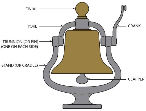
PARTS OF A BELL ASSEMBLY
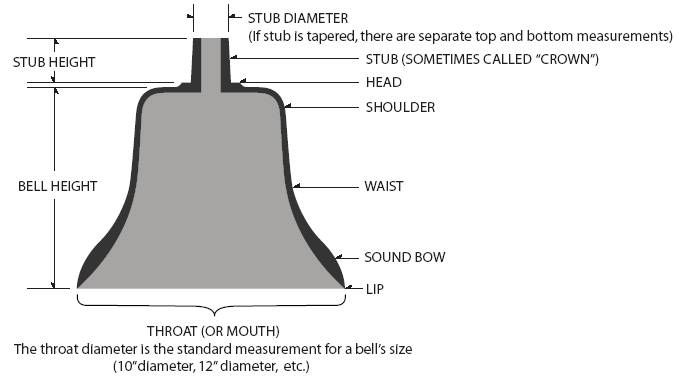
HOW TO MEASURE YOUR BELL
Article by Griffin Hamilton, used by permission of author.
BRONZE EMD BELLS
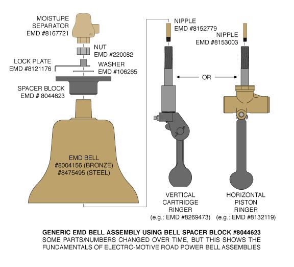
Most bells with a lip diameter of 12” or less are unlikely to be steam locomotive bells unless they are from very small locomotives. A 12” bell which also has an overall height of around 11” - including a neck drilled through its axis for a 7/8” stud - is more likely to be an Electro-Motive Division diesel-electric locomotive bell. This neck - a tapered cylinder 2” in height, approximately 1.85” diameter at the bottom, narrowing to 1.64” at the top - is a particularly good identification feature, as the bells of some other early diesel manufacturers may differ significantly. EMD bells will also have the underside around the 7/8” hole “spot faced” to a diameter of roughly 2.50” - creating a large, flat bearing surface for an air ringer.
These Electro-Motive bells (EMD part #8004156 “BELL .. Locomotive - 12 inch”) are the most commonly encountered locomotive bells in North America. Commonly called a “bell brass” or “AAR bell brass”, all nonferrous EMD bells are cast of a bronze alloy. Older EMD bells are generally unmarked and can be found with both rough cast (“as cast”) and smooth (“ground”) finishes. The majority of older bells will have the smooth finish, while a few may also have a higher polish; these polished bells were confined to applications where bell assemblies were highly visible. Most polished bells today have been polished well after delivery by individuals, not by EMD or the railroads.
Though not having the same lines as other makersí bells, these smooth EMD
bells still have an appealing, traditional shape to them. Some older bells found
on EMD locomotives will have a sharp shoulder (ìflat topî), but the basic
proportions are held across production. These ìflat topî bells have a more
ìAlco-likeî appearance than the rough cast bells. Rough cast EMD bells have
a somewhat less classic shape to them, with subtle changes in profile.
Over time, EMD went completely to bells with a rough cast finish, eventually
making obsolete bells with a smooth finish (the part number was retained to
identify virtually any bronze 12î bell on an EMD locomotive). At some point,
the rough cast bells began to feature ìEMDî and ì8004156î cast raised on
their top surface, the number being approximately 5/16î tall on earlier
castings, later being around 7/16î tall. Evidence indicates that no
factory-original EMD bell will have a smooth finish in conjunction with a cast
raised part number.
The physical quality of these bells varies- some are quite good, others have a
great number of casting flaws. The neck area is a frequent site for voids, yet
such bells with long use seem to hold up well over time. There are replacement
bronze bells cast by third parties for EMD applications... while
interchangeable, they may have a slightly different profiles;few were marked, so
further identification is problematic. A small number of recent replacement
bells will be encountered, and these can make better candidates for polishing or
other display-oriented procedures.
STEEL EMD BELLS
Available alongside the bronze bells for a time (late 1970’s-early 1980’s), EMD switched completely over to cast steel bells (EMD #8475495 “BELL .. Locomotive - 12 inch - Steel”) by the mid ‘80’s. These bells are all rough cast finish, with the EMD part number cast raised on the top surface along with miscellaneous foundry marks. Fully interchangeable, the dimensions and overall shape of these steel bells are identical to the rough cast bronze bells. Some EMD locomotives can found with replacement steel bells sold by United Knitting Machines (UKM part #276-03845), and these will have “UKM” (along with other markings) cast into the top surface.
There are cast steel bells that look like an EMD steel bell with no neck, being almost flat across the top- these generally prove to be General Electric 12” steel locomotive bells. Occasionally encountered are cast steel bells that appear to be a smooth version of the “neckless” GE-style bell.
SPACER BLOCKS
A standard mounting method on both passenger and freight EMD applications has been the “spacer block” (EMD part #8044623 “BLOCK .. Bell spacer”). This cast iron block has long been the common EMD bell/locomotive interface. Though interchangeable, there have been two revisions to the pattern, all marked “8044623” in cast raised numbers. There may be an “A” tacked onto the number, or they may have “REV A” or “REV B” cast into them on another line. Small foundry markings can be found on many specimens as well. Replacement spacer blocks have been available in the past from Power Parts Co., and they will differ from EMD blocks only in minor details.
The spacer block relies on a lock plate (EMD part #8121176 “Plate .. lock”) having a “wing” bent up against a flat on the ringer nut to keep the nut from loosening.
BELL BRACKETS
As a rule of thumb, EMD used 3/8” thick steel plate when fabricating brackets that utilize the bell spacer block, and these are often formed by bending, which makes duplication a heavy-duty chore. A few methods dispense with the spacer block, and they will be obvious.
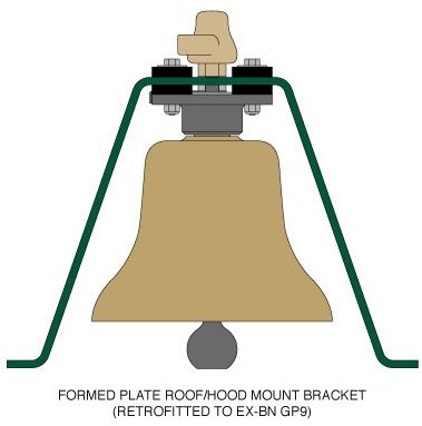 |
Roof brackets came in two basic styles: formed plate types often found on the hood between exhausts, etc., and the pedestal as found on GP18 units and much SP power. The formed plate types are of various dimensions, but are generally of 6” wide x 3/8” thick steel plate bent to make a flat-topped “A” with feet, the most consistent feature being the use of bell spacer blocks. |
|
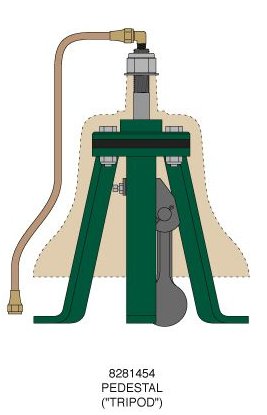
The pedestals (EMD #8281454 “PEDESTAL .. Bell”), or “tripods,” are the other basic roof mount, and are basically a ring of steel with three 1.5” wide legs of 3/8” steel welded to it. When assembled with certain ringers, the bottom of the clapper will be below the plane of the pedestal’s feet; clearance depends on these tripods being bolted onto three threaded “tapping pads” welded to the locomotive. The pedestal alone is not enough to mount the bell: EMD part #8281450 “ADAPTER .. Bell” and #8281451 “INSULATOR .. Bell” are required to make a complete assembly. |
|
 |
One of the earliest EMD bell mountings was the “Howard” stand and yoke
(EMD #8057928 “STAND .. Bell” and #8057929 “YOKE .. Bell”). This cast iron assembly looks and swings like a steam-era bell, but is configured for pneumatic ringer operation. The asymmetrical look of the stand results from being designed to accommodate an air line emerging from the left
trunnion. Howards come in a few sub-variants, some with a lockplate riveted to the yoke, some with patent information cast into the stand, etc. Generally speaking, they will all say “HOWARD” on the mounting base. “Howards” will operate correctly only with horizontal piston pneumatic ringers which allow the clapper to swing in both directions. Howards that have seen long use may suffer from worn trunnions/holes, requiring line boring/bushing to repair. Evidence shows that many Howards ended up immobilized, with the air line plumbed directly into the ringer stud instead of through the stand. Howard assemblies can be cranky, and have been considered obsolete by EMD for a number of years. |
| The “Howard” was replaced on EMD switchers in the early 1950’s by the fabricated EMD “trapezoid” bracket (EMD # 8164654 “BRACKET ASSEMBLY .. Bell”), which was the end-cab switcher standard until the end of 567-engined locomotive production. This bracket came in two major variations; the earlier version featuring two 1” x 1/4” x 20 tpi studs (applied via an arc-stud-welding gun) to attach clamps for securing a flexible hose air line. |
|
|
|
|
| The later style has one clamp assembly welded on to secure a 3/8” copper tube air line. The overall change in styles occurred somewhere around 1955, but overlapping has been noted, a few operators specifying the earlier type.
|
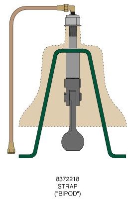 |
The “trapezoid” was displaced by the two-legged strap “bipod” (EMD # 8372218 “STRAP .. Bell mounting”) in the 1960’s, and this is - broadly speaking - simply a piece of strap steel bent into an “A” shape with feet, the bell merely sitting on top of it. This mounting uses no vibration insulator other than one (or more) steel washers between the bracket and the bell. The bipod is bolted to four small tapping pads that are welded to the top of the hood, and is typically found on SW1500/MP15 type power. |
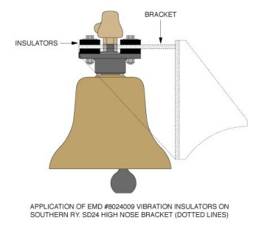 |
Most EMD bell assemblies had some form of vibration control included. All mountings featuring bell spacer blocks utilized four neoprene “insulators” (EMD # 8024009 “INSULATOR .. Vibration”) between the spacer block and the bracket, with four more between the bracket and the washers for the mounting bolts. This gave the bell assembly vibration dampening and a degree of flexibility that helped prevent problems plaguing bells in excessively rigid mountings. The “tripod” pedestals use a large, reinforced round neoprene insulator between the pedestal and the adaptor, much like an oversized EMD air horn vibration insulator/mounting pad. Both “Howards” and “trapezoids” sat on a 1” thick neoprene pad, oval in shape to match the footprint of the bases. Many of these applications also have a marine-grade plywood filler piece below this pad, the plywood being slightly “V” beveled on the underside to fit the “peak” in the top of the hood. The “bipod” strap mounting has no vibration insulators, the vibration supposedly being controlled by the less rigid strap itself, in conjunction with the minimal four-point attachment to a relatively flexible sheet metal hood. |
TRUNNION LOCATION
|
|
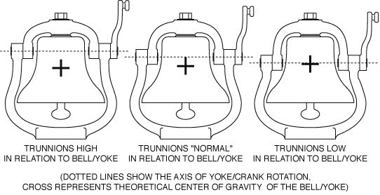
Generally speaking, the higher the trunnions are in relation to the center of gravity of the bell and yoke assembly, the more effort it will take to begin swinging the bell. Conversely, the lower the trunnions in relation to the bell/yoke CG, the less energy it will take to begin the swinging motion. Unfortunately, as the axis of the trunnions is further lowered towards the CG of the bell/yoke assembly, said assembly tends toward static balance; if this is actually achieved, the yoke/bell is then inherently unstable, and is likely to be upside down in the stand as it is to be right side up. All bells of this type are set up with the trunnion axis high enough to keep the mouth of the bell pointing down when at rest, but some are much closer to instability than others. Certain U.S. railroads and/or manufacturers had bells which tended to "tilt" towards the front or rear when at rest, and these are generally found to have a relatively low trunnion axis which accentuated any weight imbalance in the bell casting itself. the action of bell mounts with higher trunnions tend to be considered "ponderous," while lower trunnions might be considered "lively." The latter can become so extreme that it becomes difficult to achieve a pleasant cadence to the ringing. There is much argument to this day as to where the perfect compromise is found (and the disagreement has been going on for over 150 years). If the trunnions are too high for a particular bell, sometimes improvement can be had by making a heavier finial to go on top of the nut, thus raising the CG of the bell/yoke. Sometimes repositioning the bell crank on its trunnion can make a difference, as can adding a crank to the other side of the bell (usually requiring a longer trunnion). After all this is digested, there remains the question of where the clapper is pivoted in relation to the trunnion axis, and that complicates matters further. In theory, the best result is when the clapper pivot is on or above the same axis as the trunnions. The wonderful "clang... clang... clang..." cadence we love to hear is a combination of bell construction characteristics and operator skill. Even at their best, pneumatic ringers are to bells what solenoid valves are to horns/whistles. |
MOISTURE SEPARATORS
Many EMD bell assemblies feature a moisture separator that looks a bit like a miniature bell applied to the end of the bell ringer stud. The separator (EMD part # 8167721 “SEPARATOR.. Moisture”; Vapor part # 16720048; Viloco part # BR-113). It will be marked “VILOCO BR 113” and “INLET” cast raised. This accepts a 1/4” MPT air fitting at the inlet. Air enters, and swirls around the inside of the lower chamber of the separator where centrifugal force causes moisture in the incoming air to spit out of a small hole opposite the inlet. The air then flows to the upper chamber, the roof of which just clears a pipe nipple or pipe assembly screwed into the end of the tapped air passage in the ringer stud. The air then flows over the top edge of this pipe nipple and down into the ringer.
These moisture separators changed from cast bronze to cast aluminum over the years, keeping the same part numbers... regardless of material, these were not polished as originally installed. Many locomotives lost these separators after the passage of time, as they weren’t absolutely necessary for the bell to operate. Often, bells on old units ended up with common 1/4” MPT x 1/2” or 3/8” tube fittings threaded into the top of the ringer stud.
The separators are less common in later EMD hood and roof mountings, particularly with bells using “trapezoid,” “tripod” and “bipod” brackets; one reason was that their usual taller elastic stop nuts leave too few available threads. Generally speaking, Canadian-influenced railroads seem to have been the only ones who favored them to any great degree on these applications. “Howard” assemblies almost always had needle valves installed on their ringer studs, which precluded the installation of separators.
BELL RINGERS
These are pneumatic ringers engineered for specifically for compressed air, not steam. There have been two basic configurations used, both being available in single-action or double-action styles (single-action ringers depend on the air being utilized only on the power stroke, relying on the momentum of the returning clapper for the return to battery- double-action ringers use the air to actually assist the return part of the operation).
HORIZONTAL PISTON RINGERS
|
|
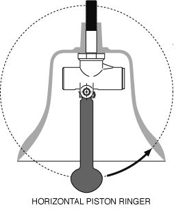
In these, the operating piston is in the horizontal plane, and the clapper is centrally pivoted, allowing it to swing fully in both directions of travel. In EMD diesel bell terms, there are generally only two companies represented: Viloco and Transportation Devices. The latter are uncommon in EMD applications compared to Alco’s, etc. The early Viloco ringers used by EMD were single action ringers having an integral ringer stud cast with the body (EMD part #8095868 “RINGER .. Internal bell”), with an octagonal end cap and a vertical groove running the length of the stud’s threads. This was superseded in the early 1950’s by an improved model (EMD #8132119 “RINGER .. Internal bell”; Viloco part #30312; Vapor part # 16730160-01). The improved model features separate stud and body, with a round end cap having two holes for a spanner wrench. |
| These later Viloco single-action ringers were the most popular of the horizontal-piston ringers, and are common enough even today; they may or may not have a needle valve fitted to the air inlet at the top, those used in Howard mountings being more likely to have one of the three different needle valves EMD favored over the course of their use. Viloco eventually developed a double-action version which saw some application in later Electro-Motive power (EMD part #8205243 “RINGER .. Internal bell - Double action”; Viloco part #30472; Vapor part #16730161-01). These can be quickly identified by the words “DOUBLE ACTION” cast into the ringer body. | |
VERTICAL CARTRIDGE RINGERS
|
|
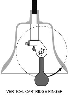
Vertical cartridge type ringers were applied to EMD engines as far back as the early 1950’s, beginning with the single action “BR-106” (EMD part #8165409 “RINGER .. Internal bell”). Later on, this part had the addition of “Single-action” added to the description to differentiate it from the “BR-106P” (EMD part #8254433 “RINGER .. Internal bell - Double action”) ringer. The difference was in the cartridge, all other components being the same. Ringers of the “106” type have been made by Prime (now part of the Dayton-Phoenix Group) and by Graham-White (also known as Salem... Graham-White refers to its products as “the Salem line”).
There are a great number of visually similar ringers as made by Prime and/or Graham-White, differing mainly in the cartridge type (single-action or double-action). The clevis hole (1/2” versus a 7/8” hole, some of the former drilled out to the latter by railroads depending on what cartridge they standardized), method of retaining the pin (traditional cotter pin versus hairpin cotter pin), and so on are some other variables. |
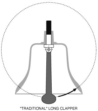
| While interchangeable across most applications, these ringers do have a few interesting physical differences- for example, the “106” has a bevel on the clevis which makes installation and removal from the “tripod’ and “bipod” brackets easier. Even within a given model, there have been variations such as decreasing the overall length of the clapper by removing a portion from the bottom, leaving a “flat.” Over time, the standard ringer has become the very common “506” ringer as made by Graham-White: a double-action ringer (EMD part #8269473) which has supplemented or superseded most of the others. |
|
|
Also a "Traditional" Long Clapper:
|
OPERATING VALVES
Some older air brake schedules (such as 6BL) will have the bell ringer valve as
a component of the brake pedestal; later EMD power may have solenoid-operated
valves, but these are not yet common items in the collectorís market. Like the
ringers, these operating valves are designed for air. EMD has used a number of
ìstand aloneî valves, but the following are the most often encountered
varieties:
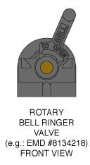 |
The older rotary valve (EMD #8003749 “VALVE .. Bell ringer throttle”) was a small cast iron unit having a short handle, often with the word “BELL” cast in or stamped on it, depending on the handle variant (cast or stamped/spot welded). Most specimens of this type will have the maker’s initials cast raised on the rear of the unit. The later - and more common - rotary valve (EMD #8134218 “VALVE .. Bell ringer throttle”) was similar in nature, but was a bit larger, and had a cast short handle in either bronze or iron, with “BELL” in raised letters inside a recessed area. This was made by Viloco (Viloco part #100, Vapor part #16720039), and can be found with “VILOCO 350” cast raised on the front of the unit, or the “350” may be replaced with a stamped “100”, depending on its age. |
PUSH-PULL VALVES
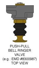 |
The “push-pull” type of bell operating valve comes in many varieties, but they all consist of a knob/cartridge assembly screwed into a cast iron body of some sort (usually a single cartridge body, but occasionally they are found in bodies accepting up to four different valve cartridges). The inlet and outlet on the body may be oriented top and bottom or both to the rear, and the cartridges may be manual, 3-way (both manual or automatic), and so on. One of the most common types is the simple manual operating valve (EMD #8300987 “VALVE .. Bell operating - Push pull type - GWS-616-1A-BH”) having a brass knob stamped “BELL”. It pulls out to operate, and pushes in to stop. A rubber dust boot extends between the front of the cartridge and the knob. |